Each chapter provides a brief introduction to the relevant connection method and is followed by a technology review to address issues that may affect the integrity of the connections. Overloading the bolts during tightening can lead to the failure of the connection for various reasons (e.g. yielding, cracking of the bolt). Flange connections are the main application of using bolts for subsea installation.
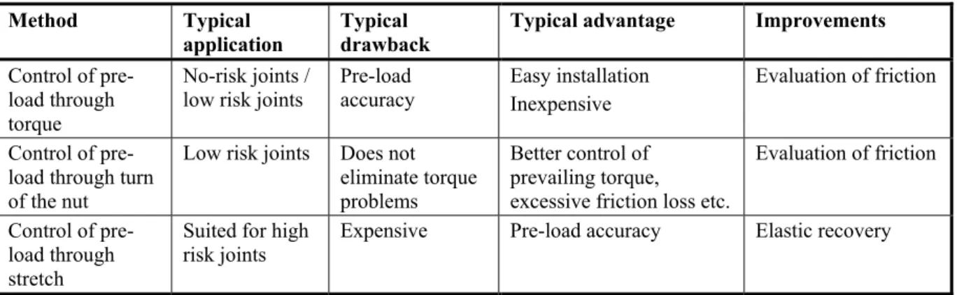
Nut Torque and Torque Control Control of preload through nut rotation. Further, a lack of awareness of the requirements for achieving bolting integrity has led to situations where it is the "man with the wrench" who actually controls the bolting installation. Implementing tools to meet expectations, such as risk assessment, competency management and control of practices used.
One of the most important tasks for screw flange joints is to prevent leakage of liquid or gas. The release depends on the initial tension of the screw, temperature changes and the variable pressure of the contained liquid or gas. Seal pressure in a compact flange is independent of external load and bolt preload.
Essentially, the preload should be as high as is acceptable, while striving for an even distribution of the preload.
Uncertainties and challenges
Stretch control should be used for all high risk joints as this will provide preload accuracy of approximately +/- 10%, while torque can provide accuracy of approximately +/- 25% (Ref. /1/). When installing torque, it is essential that friction is considered in the process. Consequently, at a preload with a given applied torque, the lack of lubricant control can change the friction factor and result in an actual preload that can be 60 to 80% of the expected value.
The technology for performing high integrity bolting is available in the UKOOA report (Ref. /1/). The essential elements of the UKOOA report should also be implemented for the offshore industry in Norway (Figure 1). The aspects of offshore industry practice related to bolt installations are current.
To achieve the most robust bolted joint, the operator must emphasize each phase in the life cycle and perform a risk and consequence assessment. Based on errors/leaks, the list for a given tier can be updated to ensure that the items that caused the leak are corrected.
3 S-LAYING GIRTH WELDS OF LARGE X70 TYPE PIPES
- Introduction .1 General
- Welding
- Vessel types
- Plastic strain and ECA
- Technological status
- Limitations for this joining method
- Uncertainties and challenges
- Important parameters for robust joints
- Introduction
- Onshore welding of prefabricated joints
- Offshore welding on installation vessel
- Welding defects and NDT
- J-lay vessels
- Application
- Technological status
- Limitations for this joining method
- Uncertainties and challenges
- Important parameters for robust joints
- Introduction
- Application in pressurised equipment
- Technological status .1 Metallurgical status
- Experience in pressurised equipment
- Research
- Limitations for the use of API 5L grade X65 in pressure equipment The use of API 5L, grade X65, in pressure equipment is mainly limited as follows
- Uncertainties and challenges
- References Reference no
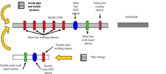
Then the double joints are rolled or hoisted onto the support rollers of the main welding line. When the alignment of the joints in the main line and preheating (if necessary) are completed, the alignment clamp is activated to hold the pipe in place and the weld ground fit is performed by automatic GMAW (or GTAW) welders. Other considerations in the ECA may result in restrictions on the geometry of the welding shield, the depth of the undercut and the maximum allowable high-low due to the resulting stress/strain concentrations.
The LBZs are associated with the sections of the HAZs that experience grain enlargement during the welding operation. The implication of the results obtained from toughness testing when LBZs are encountered should be evaluated. The welding parameters used during welding of the individual test pieces should therefore be the same for the same pass in the same peripheral position.
If it becomes necessary to change a batch of consumables, batch testing shall be performed to verify that the new batches of consumables will produce deposited weld metal nominally equivalent to those used for welding procedure qualification in terms of chemistry and mechanical properties. o Consumables, including SAW flux, must be maintained in a reliable, dry .. condition and stored and handled according to a procedure that meets or exceeds the manufacturer's recommendations to meet the guaranteed maximum value for hydrogen in the weld metal. o Classification, designation, purity and dew point of shielding and back gases must comply with recognized standards such as ISO 14175 or EN 439. In general, J-laying introduces low installation loads, depending on the water depth and thus the curvature and weight of that part of the pipeline , hanging from the vessel. Assemblies are transferred from the deck to the upper part of the J-lay tower for intermediate storage (several can be stored in the tower) using an integral lifting device.
The internal line-up clamp with copper backing for the weld is inserted from the top using an integrated winch in the J-lay tower. Due to the configuration of the scanned weld (vertical position), thereby preventing large scanner units from rotating the pipe, phased array systems with only one probe on each side of the weld are applied in combination with Time of Flight Diffraction (ToFD). However, the design standard/formulae may lead to significantly different wall thicknesses and therefore the actual weight of the pipe may be limiting in terms of installation.
To prevent damage to the FJC when acting on the roller casings, the FJC had to be allowed to cool sufficiently, i.e. Preheating the base material is often used to limit the hardness in the weld. Lack of fusion can also be caused by oxidation of the surfaces in the welding preparation due to insufficient protection by the shielding gas.
Undercuts are a groove fused into the base material at the toe or root of the weld and not filled with weld metal. Due to the limited height of the welding passages, the imperfections are often small.
7 DEEPWATER PIPELINE HYPERBARIC REPAIR WELDING 7.1 Introduction
- Technological status
- Limitations
- Uncertainties and challenges
- Important parameters for robust joints
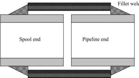
This welded sleeve joining method will be applicable for replacing damaged sections of deep water pipeline regardless of diver assistance and water depth. The method is currently being qualified for pipe steel outside diameters in the 8" to 48" range and for API 5L materials in grades X60 to X70. However, today further development of PRS - with Statoil at the helm - is focused on the MIG-based system developed by Cranfield University.
The new RPRS concept, the Welded Sleeve concept, has been developed to eliminate the need for submersible weld repair in moderate and deep water depths as an adjunct to mechanical joints for large diameter pipelines. The damaged length of pipeline is replaced by a coil of similar dimensions and grade of material. This method presents fewer challenges in terms of alignment of the two ends of the pipe to be joined and does not require preparation of the weld bevel.
The main challenge has been to qualify a fillet weld profile such that the sleeve repair joint assembly constitutes the same structural capacity as a. The deep water welding hyperbaric sleeve repair method is expected to be qualified for offshore pipeline repair in approximately one year, for standard carbon steel material. For the welded sleeve, Non-Destructive Testing of the filled weld is not feasible, bringing an increased requirement for welding procedure qualification and simulation of underwater conditions during laboratory testing.
Offshore welding qualification must be based on a record of all applicable welding parameters to confirm that welding has been performed within the qualified parameter window. It achieves an acceptable high fracture toughness, which allows some margin in the tolerances of possible defects in the root of the weld. The qualification of the technology has been transferred to the DNV approval statement, which means that the new technology is expected to be demonstrably suitable for use with the remaining planned qualification activities.
The qualified welding procedure includes project specific conditions in all aspects (base material, weld deposit material, dimensions, external pressure, habitat environment, gap between sleeve and coil / pipeline, welding parameters, weld profile). Tolerances on the level and variation of the gap between the outer diameter of the pipeline/coil and the inner diameter of the sleeve.
8 WELDING OF 13CR MARTENSITIC - 22CR AND 25CR DUPLEX STAINLESS STEELS FOR SUBSEA APPLICATIONS
Introduction
8.2 13Cr Martensitic stainless steels 8.2.1 Application
- Technological status
- Limitations for joining of 13Cr
- Uncertainties and challenge
- Important parameters for robust joints
- Duplex stainless steels .1 Application
- Technological status
- Limitations for joining of duplex
- Uncertainties and challenges General
- Important parameters for robust joints
The fact that the 13Cr HAZ of the anode attachment welds is not PWHT is believed to give. One of the main remaining issues is to address the susceptibility to HISC when the welds are exposed to CP. It is not recommended according to current practice to use filler materials other than 25Cr duplex stainless steel.
As will be detailed later, there are issues associated with performing ultrasonic inspection of duplex stainless steels. Since the 13Cr pipe perimeter welds are mainly welded with double stainless steel filler, special requirements are required for the automated ultrasonic testing (AUT) system. 22Cr and 25Cr duplex stainless steels have been widely used within subsea units such as manifolds and X-mas trees for over 20 years.
Duplex stainless steel is also a commonly chosen material for umbilical tubing and other types of instrument tubing. There have been a number of high profile failures of duplex stainless steel exposed to CP due to HISC. If duplex stainless steel is kept in the temperature range 750 to 950 °C for too long or cooled slowly through this temperature range, intermetallic phases that have a detrimental effect on the material's toughness and corrosion priorities (eg sigma phase) will be formed.
There are certain challenges in performing UT of duplex stainless steels compared to other steels. Ultrasonic testing of duplex stainless steel and dissimilar metal welds is a very laborious and painstaking task, but it can be done with care. There are currently several widely recognized standards that address critical issues related to duplex stainless steel welding.
Cooling of the weld metal is however faster in a fillet weld due to the geometry of the joint. When repair welding is performed on duplex stainless steel welds, the HAZ of the repair weld will undergo additional heating cycles compared to the original weld. To be representative, repair welding procedures should be done such that the HAZ of the repair weld is located within the weld metal and the HAZ of the original weld.