The report summarizes the most important relevant standards affecting the management of the integrity of solid flow lines (Section 3). The key to managing the integrity of solid pipelines is to apply subject matter expertise to understand threats in the context of risk.
Scope of document
Definition: Rigid flowline
Abbreviations
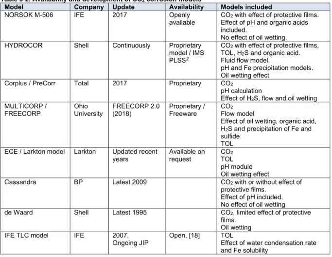
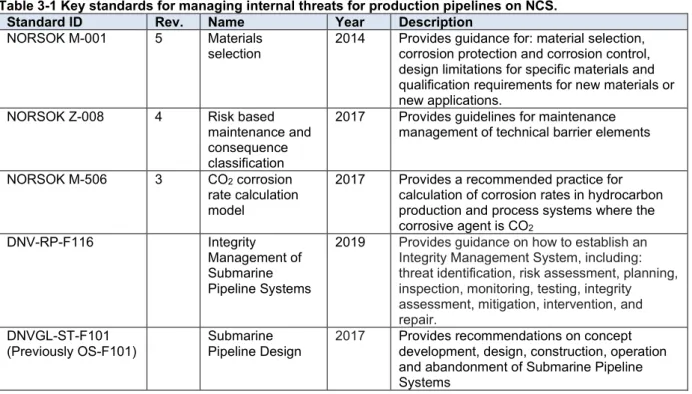
2017 Provides a recommended practice for calculating corrosion rates in hydrocarbon production and process systems where the corrosive agent is CO2. Pipeline Design 2017 Provides recommendations on concept development, design, construction, operation and decommissioning of submarine pipeline systems.
Introduction
The first petroleum law of 1985
The Piper Alpha disaster
North Sea Offshore Authorities Forum
Norsk Sokkels Konkurranseposisjon (NORSOK)
Samarbeid for sikkerhet
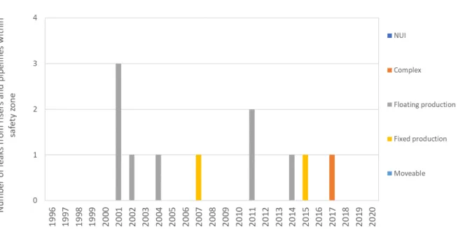
Development under defined risk and accident conditions with the potential to cause major accidents, [4] * within the safety zone. One of the major leaks on the Norwegian shelf outside the safety zone was the rupture of the Shell Draugen Garn West flowline in 2003.
![Figure 4-3. Risk exposure from leakages weighed from risk potential [4].](https://thumb-eu.123doks.com/thumbv2/9pdfnet/19450435.0/12.892.108.768.70.432/figure-4-risk-exposure-leakages-weighed-risk-potential.webp)
Advances in standards and recommended practices
Pipeline design
Pipeline remaining strength of corroded pipelines - Defect sizing
Integrity management
Advances in prediction models
Advances in materials selection for rigid flowlines
This solution became interesting from 2000 to PT, e.g. installation at the current Aasta Hansteen project. When using stainless steel and coated solutions, corrosion management had to be modified to include other relevant failure modes than carbon steel.
Technical advances in monitoring equipment and software
The project idea is to install distributed sensors along the flowline to provide a self-monitoring pipeline. Currently, the trend is to use non-intrusive point monitoring equipment underwater and intrusive equipment on top, see sections 5.3 and 5.6.
Data driven corrosion management and integrated operations
Material selection for rigid flowlines
Internal threats for rigid flowlines
- CO 2 corrosion
- General H 2 S corrosion
- Injected acid corrosion
- Top of line corrosion
- Under deposits corrosion
- Microbiologically induced corrosion
- Erosion-corrosion
- Galvanic corrosion
- Preferential weld corrosion
- Elemental sulphur
- Carry-over of glycol
- O 2 corrosion
- Cracking mechanisms
- Liquid metal embrittlement and amalgamation
- Internal erosion
Erosion corrosion is a synergetic effect of flow-induced mechanical removal (erosion) and chemical removal (corrosion) of the pipeline material. The pitting corrosion rate can be severe, leading in some cases to penetration of the pipeline wall in 3-12 months [16].
Monitoring equipment
- Multiphase flowmeters
- Erosion monitoring
- Sand monitoring
- Sensors
- Corrosion and erosion probes and coupons
For ER probes, the principle of electrical resistance uses a linear increase in electrical resistance in the corroding element as the cross section of the element corrodes. A potential is applied to a freely corroding sensing element and the resulting (linear) current response is measured to establish a linear relationship between potential and current. The current required to maintain a certain voltage shift is directly related to the corrosion on the electrode surface and the corrosion rate can be calculated.
Corrosion coupons are simply coupons in a material representative of the flowline material that is intrusively exposed to the flow. The corrosion rate is calculated assuming uniform corrosion over the entire surface of the coupon in accordance with the NACE RP0775 standard. Corrosion coupons are not normally used for subsea pipelines due to the challenges and logistics associated with subsea probe replacement.
Corrosion models - Prediction of corrosion rates
To compensate for this, the partial pressure of a gas is multiplied by a fugacity constant to obtain the fugacity used in the CO2 model.
Predictive techniques applied for flowline asset integrity management
- General
- Prediction and analysis - Integrity operation window
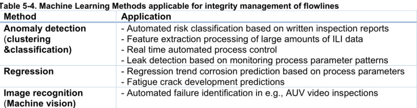
- Machine Learning applied for flowline asset integrity management
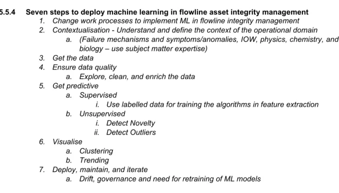
- Seven steps to deploy machine learning in flowline asset integrity management
However, together the parameters provide a picture of the overall situation and can be used to monitor potential corrosion threats and track any changes in the system. Perfect control of these parameters does not guarantee control over the condition of the pipeline. However, in combination with ILI, the condition of the pipeline can be estimated. Change work processes to implement ML in flowline integrity management. 2. Contextualization - Understand and define the context of the operational domain.
In order to handle the implementation of AI in asset integrity management, it is therefore important to set work processes and organizational requirements to handle the implementation, reporting and management of the ML process. For ambient temperature on the Earth's surface, the "operating window" is -88 in Antarctica to +58. BSSE – Bureau of Safety and Environmental Enforcement of the US Department of the Interior (www.bsee.gov).
Note that ML algorithms can handle multivariate correlation in hyperspace, which is one of the great strengths of the ML method. University of Stavanger thesis on machine learning based on ILI data from the Ula to Ekofisk pipeline inspection, based on 2010 ILI data from a 20-inch ultrasonic inspection tool [38].
Inspection methods for internal integrity
- General
- MFL – Magnetic flux leakage
- UT – Ultrasound technology
- ART – Acoustic resonance technology
- EC – Eddy current
- EMAT - Electromagnetic acoustic transducer
- Combined ILI tools
- External inspection of internal integrity
- Spool/equipment retrieval
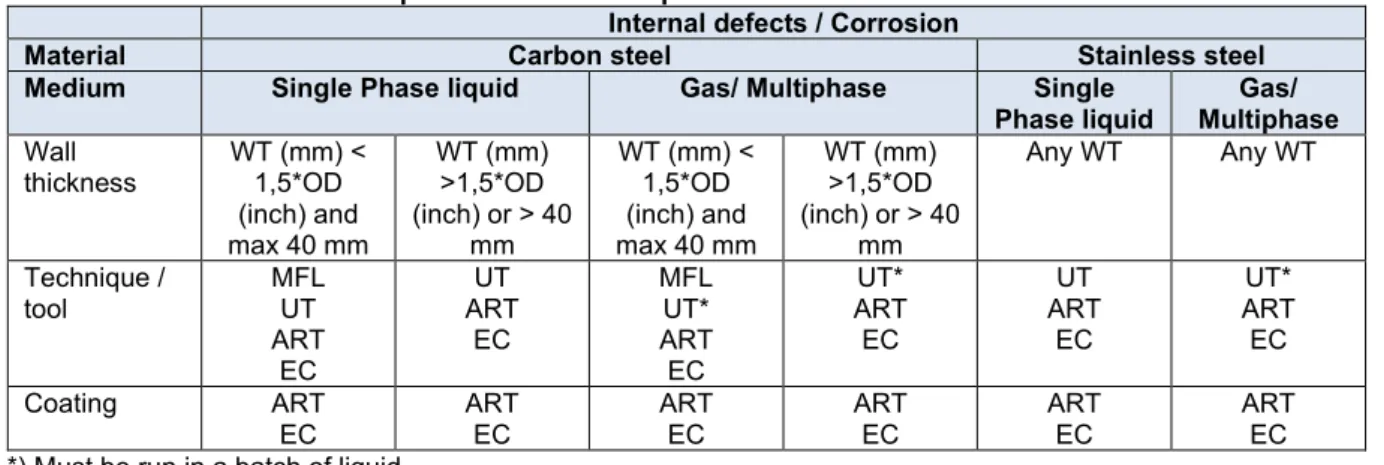
- Selection of inspection method for internal defects in flowlines
Ultrasound technology (UT) is used as an ILI tool to measure the absolute thickness of the wall. ILI tools usually use combined techniques to improve the characterization and quality of the inspection. Basically, the combination must be chosen in relation to the nature of the flow line and its operation, as well as geometric and operational limitations.
Limitations on the technology relate to access to the entire perimeter of the pipeline and the inspection speed, which means that it is mainly suitable for spot checks of unburied pipelines. The detection / size of defects mentioned in Table 5-7 is strongly related to the accuracy of the method used. The advantage of the free-swimming tool is the range and the speed of the inspection.
The connected solution has a limitation when it comes to the length of the pipeline and the complexity of the pipeline profile. The limitation for robotic vehicles is related to the length of the pipeline caused by the battery capacity of the vehicle.
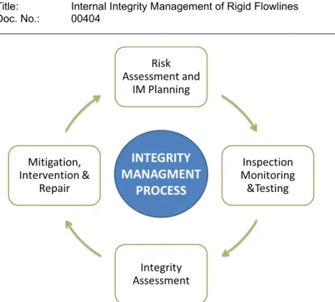
Workflow for integrity management
- Regulatory requirements
- Risk Assessment and IM Planning
- Inspection, Monitoring & Testing
- Integrity Assessment
- Mitigation Intervention & Repair
- Review and update risk assessment and plans
To ensure that risk assessment is carried out consistently, the approach to risk should be documented in strategies and procedures. It is recommended that for each of the degradation mechanisms (threats) identified, one or more barriers should be established to enable ALARP to manage the threat. The PoF should be considered for each threat and component according to the process established by the operator.
The consequence of failure (CoF) must be considered for each threat and component according to procedure established by the operator. The recommended inspection intervals based on the risk location in the risk matrix must be defined by the operator. The monitoring activities must be linked to threats and barriers (see section 5.7.2.2) to explain the reason why the activity must be done.
The inspection, monitoring and testing activities must be carried out according to the risk assessment and integrity work plan (IWP) established in section 5.7.2.5 above. As part of the annual integrity review, the risk assessment program and integrity work plan should be reviewed and updated as required.
The unknown unknowns
Cost savings in integrity management activities simply mean that the company now accepts a higher level of uncertainty and corresponding risk. The flow lines have been treated with corrosion inhibitor and the corrosion probes show negligible corrosion rates on both sides of the flow line. However, during an in-line inspection of the flow lines, severe top-of-line corrosion attacks were discovered at locations where the flow lines crossed the river.
Root cause analysis revealed that the drains were unburied and directly exposed to the fast-flowing water in the river. This cooled the flow tubes and caused high condensation rates and correspondingly high local corrosion rates at the top of the line [48]. Severe top-of-line corrosion was not anticipated in the design because knowledge of top-of-line corrosion had not advanced far in the late 1970s, and the pipeline was not expected to be exposed to river water.
During operations, top-of-line corrosion was not detected because the corrosion management strategy of using corrosion inhibitor and monitoring corrosion rates at the ends of the pipeline was not effective in detecting top-of-line corrosion. Headline corrosion was experienced as early as 1960 (Lacq sour gas field in France), however this knowledge was not shared until 1981, [49].
Turning data into wisdom
Collective mindfulness
How to meet the future
13] ISO 21457, Materials selection and corrosion control for oil and gas production systems, International Organization for Standardization, 2010. Al-MoubarakiI, “Peak Corrosion: Causes, Mechanisms and Mitigation Using Corrosion Inhibitors,” Arabian Journal of Chemistry, p . Sliem et al., "Undercoat Corrosion Monitoring for the Oil and Gas Industry: A Review".
Jiaa and et al, “Microbiologically influenced corrosion and current mitigation strategies: A state of the art review,” International Biodeterioration & Biodegradation, pp. Husby and et al, “Corrosion of 22%Cr and 25%Cr duplex stainless steel in produce water with small amounts of oxygen,” 16th Nordic Corrosion Congress, Stavanger, 2015. 24] ISO 15156-1, “Materials for use in H2S- containing environments in oil and gas production — Part 1: General principles for selection of crack-resistant materials", ISO, 2020.
25] ISO 15156-3, Materials for use in H2S-containing environments in oil and gas production — Part 3: Crack-resistant CRAs and other alloys, International Organization for Standardization, 2020. McIntyre, "Mercury Liquid Metal Embrittlement Of Alloys For Oil And Gas Production and Processing,” CORROSION, pp.
Appendix 1 – Relevant standards
ISO 15156-3 4 Crack-resistant CRAs (corrosion-resistant alloys) and other alloys 2020 Provides recommendations for the use of CRAs and other alloys for use in environments containing H2S. land pipeline 2019 Provides recommendations on managing the integrity of the land pipeline system throughout its life cycle ISO 19345-2 1 Life cycle integrity. Offshore Pipeline 2019 Provides recommendations on managing the integrity of an offshore pipeline system throughout its life cycle. Title: Management of Internal Integrity of Rigid Flow Lines Revision: 3. Page 60 of 69 Table 8-4 Relevant ASME, API Standards and Recommended Practices. Provides guidance in evaluating the pressure holding capability of corroded pipelines and ASME pressure piping systems.
3 Fitness-For-Service 2016 Provides guidance on how to perform quantitative evaluations to demonstrate the structural integrity of an in-service. 2021 Provides guidance and limitations for the selection and use of materials and for the protection of pipelines against external and internal corrosion. 2017 Provides guidelines for the design, installation, operation, repair and decommissioning of subsea production systems, including pipelines and terminations.
2017 Provides guidance on the management and application of reliability and integrity management (RIM) engineering techniques. 2019 Provides guidance on how to use the "Plan-Do-Check-Act" cycle for a pipeline integrity management program, which is a set of policies, processes, and procedures to manage risk through continuous assessment and improvement activities.
Prediction of top-of-line corrosion is also included, as well as models for H2S corrosion and organic acid corrosion. The model includes H2S effects, effect of acetic acid and calculation of top-of-line corrosion. In addition to the models discussed above, the Institute of Energy Technology has developed a dedicated top-of-line corrosion model, which is dependent on the water condensation rate and the amount of iron that can be dissolved in the condensate (11).
The top-of-line corrosion rate then becomes dependent on the water condensation rate and the amount of iron that can be dissolved in the condensation water. Top-of-the-line corrosion is now included in several of the corrosion models, and they all build on this principle. Of the models described above, top-of-line corrosion is included in de Waard, HYDROCOR,.
The presence of organic acid in the gas can significantly increase the top-of-line corrosion rate, as it increases the amount of iron that can be dissolved in the condensing water before protective corrosion films are formed. Dugstad, "Top of Line Corrosion and Water Condensation Rates in Wet Gas Pipes", CORROSION/2007, Paper no.
Appendix 3 – Relevant monitoring parameters
![Figure 4-1. Historical overview of the Norwegian regulatory regime, [1].](https://thumb-eu.123doks.com/thumbv2/9pdfnet/19450435.0/9.892.110.768.652.941/figure-4-1-historical-overview-norwegian-regulatory-regime.webp)
![Table 5-1 Adjusted and expanded from [14]](https://thumb-eu.123doks.com/thumbv2/9pdfnet/19450435.0/18.892.103.791.736.1151/table-5-1-adjusted-and-expanded-from-14.webp)