Input-Output Reference
What’s different about EnergyPlus Input and Output?
- EnergyPlus Input Processing
- General Input Rules
- EnergyPlus Output Processing
Rules about the Input Data Dictionary are shown in the Interface Developer's Guide (there is a lot of similarity and overlap), but most users can see the IDD (Input Data Dictionary) as an additional quick reference for EnergyPlus. The input data file is the primary file that EnergyPlus uses to create the building simulation. The inputs are order-independent; data can appear in any order and will be retrieved and sorted as needed by the EnergyPlus simulation modules.
Each Alpha string in the input data file (aka alpha field length) can be up to 100 characters in length. Any Alpha string (including the Section and Class/Object keywords) is mapped to uppercase during processing, unless the "retaincase" flag marks the field in the IDD. The main drawback with this is that the error messages output by the input processor will be in UPPER letters and may not appear exactly as input.
Txt – reports with a .txt extension have spaces as "delimiters", but only a few of them are actually formatted as you might expect: where multiple spaces make printing with a non-proportional font produce readable results.
IDD Conventions
- IDD – IP Units
Most EnergyPlus reports can be easily viewed in current spreadsheet programs – or other software that can handle “separate variable” reports. These report files (directly from EnergyPlus) will be named something like "eplus
Default values are only populated if the field falls within \min -fields or the actual value. These can be used by input and output interfaces to represent values in the IP system. As noted, if the IP units are "default" (first block below), no \ip units are expected in the field.
Input – Output Descriptions (Document)
- Input Descriptions
- Output Descriptions
The final field in an IDD class object or in an IDF object is terminated by a semicolon. The \ designations will show various information about the objects as described above in the IDD conventions discussion. Any violations of the \minimum, \maximum fields are automatically detected and messages will appear in the standard error file.
Even if items are not used for a particular object (eg Multiplier in FenestrationSurface: Detailed and type = Door), the field must be included unless it is the last field in the object. In the descriptions below, we will try to show the output of each object as well as each of the described outputs. The IDF screen has the same information in an IDF-ready form (ie, you can copy and paste it into your input file using a text editor).
All the same information appears in a slightly different form and defaults to "hourly" reporting frequency (which of course can be changed when you put it in your input file).
Using EnergyPlus as a Library
- State API
- Functional API
- Runtime API
- Data Exchange API
- Full Examples
- Building and Linking
As of version 9.4, the API was improved with the ability to more reliably "reset" the state of the simulation. By refactoring the 17,000 global and static variables in the program, the state object now holds all of the program's state, and threads will not be cross-linked. The interface developers have built on top of EnergyPlus have mostly interacted with the simulation in the traditional way.
In the following subsections, the API is presented with examples in both C and Python. Everything from the current time step to the part load ratio of the water side economizer is tracked in the state of a functional simulation. Note that the variable to be used is required and if the api data is not completely ready in the callback, it just returns and waits.
Once the code is compiled, it must be linked into the EnergyPlus shared library, which is also found in the root of the EnergyPlus installation.
Group – Simulation Parameters
- Version
- Inputs
- Timestep
- Inputs
- ConvergenceLimits
- Inputs
- Building
- Inputs
- SurfaceConvectionAlgorithm:Inside
- Inputs
- SurfaceConvectionAlgorithm:Outside
- Inputs
- HeatBalanceAlgorithm
- Inputs
- Inputs
- ZoneAirHeatBalanceAlgorithm
- Inputs
- ZoneAirContaminantBalance
- Inputs
- Outputs
- Outputs
- ShadowCalculation
- Inputs
- Output:Diagnostics
- Inputs
- Output:DebuggingData
- Inputs
- Output:PreprocessorMessage
- Inputs
- Inputs
- SimulationControl
- Inputs
- Inputs
- Meter:Custom
- Inputs
- Meter:CustomDecrement
- Inputs
- Custom Meter Examples
- Simulation Parameter Outputs
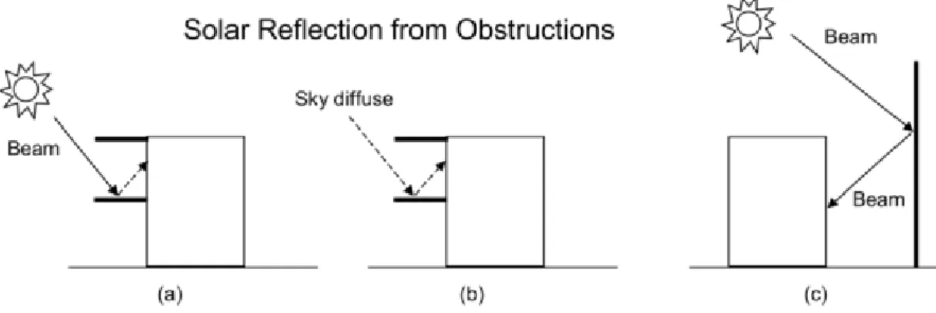
EnergyPlus repeatedly "runs" the first day of the environment either until it reaches the "maximum number of heating days" or the convergence criteria are met. Reflection from the ground is calculated even if the reflections option is not used; l but then the ground plane is considered unobstructed, i.e. the shadow of the ground from the building itself or from obstacles such as neighboring buildings is ignored. If Yes is selected, the hourly shading portion of all surfaces will be exported as a CSV file, naming it as "output file prefix + shading" (default name is "eplusshading.csv" if no file prefix is specified output).
This field is used to change the effective heat capacitance of the zone air volume. This field is used to change the effective moisture capacitance of the zone air volume. This field is used to change the effective carbon dioxide capacitance of the zone air volume.
This field is used to change the effective overall contaminant capacity of the zone air volume.
Group – Compliance Objects
- Compliance:Building
- Inputs
Group – Location – Climate – Weather File Access
- Site:Location
- Inputs
- Site:VariableLocation
- Inputs
- Inputs
- Outputs
- Longer Design Periods
- Inputs
- Inputs
- RunPeriod
- Inputs
- Inputs
- Inputs
- Inputs
- Site:WeatherStation
- Inputs
- Site:HeightVariation
- Inputs
- Inputs
- Site:GroundTemperature:Shallow
- Inputs
- Site:GroundTemperature:Deep
- Inputs
- Inputs
- Field: Soil Thermal Conductivity The thermal conductivity of the soil, in W/m-K
- Field: Soil Density The bulk density of the soil, in kg/m3
- Field: Soil Specific Heat The specific heat of dry soil, in J/kg-K
- Field: Average Annual Ground Surface Temperature
- Field: Phase Shift of Minimum Surface Temperature This is day of the year which has the lowest ground surface temperature
- Inputs
- Site:GroundDomain:Slab
- Inputs
- Outputs
- Site:GroundDomain:Basement
- Inputs
- Outputs
- Inputs
- Site:GroundReflectance
- Inputs
- Inputs
- Site:WaterMainsTemperature
- Inputs
- Site:Precipitation
- Inputs
- RoofIrrigation
- Inputs
- Solar and Visible Spectrum Objects
- Site:SolarAndVisibleSpectrum
- Inputs
- Site:SpectrumData
- Inputs
- Climate Group Outputs
- Weather Data Related Outputs
- Site Outdoor Air Drybulb Temperature [C]
- Site Outdoor Air Dewpoint Temperature [C]
- Site Outdoor Air Wetbulb Temperature [C]
- Site Outdoor Air Humidity Ratio [kgWater/kgAir]
- Site Outdoor Air Relative Humidity [%]
- Site Outdoor Air Barometric Pressure [Pa]
- Site Wind Speed [m/s]
- Site Wind Direction [deg]
- Site Sky Temperature [C]
- Site Horizontal Infrared Radiation Rate per Area [W/m2]
- Site Diffuse Solar Radiation Rate per Area [W/m2]
- Site Direct Solar Radiation Rate per Area [W/m2]
- Site Total Sky Cover []
- Site Opaque Sky Cover []
- Site Precipitation Depth [m]
- Site Ground Reflected Solar Radiation Rate per Area [W/m2]
- Site Ground Temperature [C]
- Site Surface Ground Temperature [C]
- Site Deep Ground Temperature [C]
- Site Simple Factor Model Ground Temperature [C]
- Site Outdoor Air Enthalpy [J/kg]
- Site Outdoor Air Density [kg/m3]
- Site Solar Altitude Angle [deg]
- Site Solar Hour Angle [deg]
- Site Snow on Ground Status []
- Site Daylight Saving Time Status []
- Site Day Type Index []
- Site Mains Water Temperature [C]
- Site Precipitation Rate [m/s]
- Site Precipitation Depth [m]
- Water System Roof Irrigation Scheduled Depth[m]
- Water System Roof Irrigation Actual Depth[m]
- Outputs for local temperature/wind speed calculations
- Zone Outdoor Air Wetbulb Temperature [C]
- Zone Outdoor Air Wind Speed [m/s]
- Surface Ext Outdoor Dry Bulb [C]
- Surface Ext Outdoor Wet Bulb [C]
- Surface Ext Wind Speed [m/s]
- System Node Temperature [C]
This field represents the facility's time zone (relative to Greenwich Mean Time or 0. meridian). Valid days of the week (Sunday, Monday, Tuesday, Wednesday, Thursday, Friday, Saturday) or special days (SummerDesignDay, WinterDesignDay, CustomDay1, CustomDay2) must be entered in this field. Valid days of the week (Sunday, Monday, Tuesday, Wednesday, Thursday, Friday, Saturday) can be entered in this field.
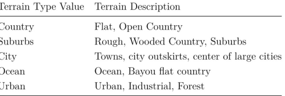
DifferenceScheduleDryBulbValue – values in the schedule are subtracted from the dry bulb temperature value (+ values then would be less than the dry bulb temperature, -values would be greater than the dry bulb temperature) for the temperature value of the resulting sky. DifferenceScheduleDewPointValue – values in the schedule are subtracted from the dew point temperature value (+ values then would be less than dew point temperature, -values would be later than dew point temperature) for the temperature value of the resulting sky. The measured conditions at the weather station (i.e. the weather file) are used by EnergyPlus in conjunction with the Terrain field of the Building object, or optionally with the Site:HeightVariation object (see below), to calculate the local variation in atmospheric properties in the function of height above the ground.
This is the name of the undisturbed soil temperature object used to determine the soil temperature. This is the value of the heat flux supplied to the GroundDomain as a boundary condition. This is the name of the other side boundary condition model used for the basement floor surface.
This is the value of the heat flux supplied to soil domain as a boundary condition for the basement walls. This is the value of the heat flux supplied to soil domain as a boundary condition for the basement floor. The ground temperature is reported in degrees C – this is a user-specified input (object: . Site:GroundTemperature:Shallow) per month.
Ground temperature is reported in degrees C – this is a user specified input (object: . Site:GroundTemperature:Deep) per month. The Site Simple Factor Model Ground Temperature is reported in degrees C - this is a user specified input (object: Site:GroundTemperature:FCfactorMethod) per month or derived from the weather file as stated in the description of the object. The dry bulb temperature of the outside air calculated on the height above ground of the center of gravity of the zone.
The outdoor bulb dry air temperature calculated at the height above ground of the center of the surface.
Group – Schedules
- Day Type
- ScheduleTypeLimits
- Inputs
- Day Schedules
- Schedule:Day:Hourly
- Inputs
- Schedule:Day:Interval
- Inputs
- Schedule:Day:List
- Inputs
- Week Schedule(s)
- Schedule:Week:Daily
- Inputs
- Schedule:Week:Compact
- Inputs
- Schedule:Year
- Inputs
- Schedule:Compact
- Inputs
- Schedule:Constant
- Inputs
- Schedule:File
- Inputs
- Outputs
- Schedule:File:Shading
- Inputs
The lower (minimum) limit value for the schedule type must be entered in this field. The upper (maximum) limit value for the schedule type must be entered in this field. If "No" is entered, the value that occurs at the correct minute in the hour will be used as the schedule value.
This field contains the name of the day schedule (any of the Schedule:Day object names) to be applied for the days referenced in the previous field. This field must contain a unique (among Schedule:Year, Schedule:Compact, and Schedule:File) identifier for the schedule. This field starts with "By:" and contains the end date for the schedule period (can be more than one).
This field begins with "For:" and contains the appropriate days (refer to the compact weekly schedule object above for complete description) for the 24 hour period to be described. This field contains the end time (again, refer to the interval day schedule discussion above) for the current days and day schedule being defined. This field contains the name of the file that contains the data for the schedule.
No" is entered, then the value that occurs at the appropriate minute in the hour will be used as the schedule value. Note that this is identical to an hourly file because there are 60 minutes per item - the number of hours defaults to 8760 and the column separator defaults to a comma. If "Yes" the schedule jumps forward an hour in the CSV on the "spring forward" day and repeats an hour on the "fall back" day.
If "No", the schedule is read and applied in standard time, without adjusting for daylight saving time (RunPeriodControl:DaylightSavingTime). This field contains the name of the file that contains the data for the shading schedules.
Group – Surface Construction Elements
- Specifying the Building Envelope
- Material and Material Properties
- Material
- Inputs
- Material:NoMass
- Inputs
- Material:InfraredTransparent
- Inputs
- Material:AirGap
- Inputs
- Inputs
- Outputs
- Inputs
- Inputs
- Outputs
- Inputs
- Outputs
- Inputs
- Inputs
- Inputs
- Inputs
- Inputs
- Inputs
- Surface Outputs
- Internal Cell Outputs
- Materials for Glass Windows and Doors
- WindowMaterial:Glazing
- Inputs
- Inputs
- Glass Optical Properties Conversion
- Conversion from Glass Optical Properties Specified as Index of Refraction and Transmittance at Normal Incidence
- Inputs
- Outputs
- WindowMaterial:Gas
- Inputs
- Inputs
- WindowMaterial:Gap
- Inputs
- Inputs
- Inputs
- Inputs
- WindowMaterial:Shade
- Inputs
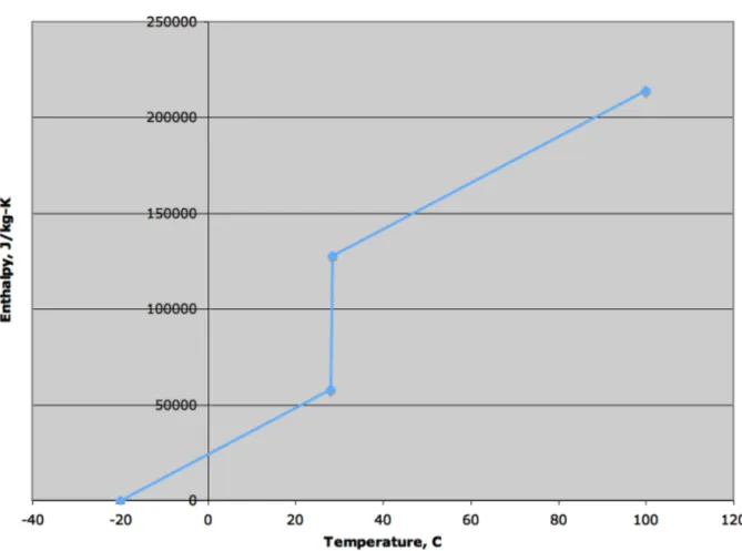
This field is used to enter the temperature-dependent coefficient for the thermal conductivity of the material. This field is used to specify the temperature of the temperature-enthalpy function for the base material. This field is used to specify the temperature of the temperature conductivity function for the base material.
The visible transmittance and reflectance properties of the window are used in the daylight calculation. Transmittance at normal incidence was averaged over the solar spectrum and weighted by the response of the human eye. Front-side reflectance at normal incidence averaged over the solar spectrum and weighted by the response of the human eye.
Backside reflectance at normal incidence was averaged over the solar spectrum and weighted by the response of the human eye. The extinction coefficient was averaged over the solar spectrum and weighted by the response of the human eye (m−1).